

-
Date:2026-01-20

-
Page View:57

The installation method of a vortex flow meter has a decisive impact on the accuracy, stability, and reliability of its measurement results. Improper installation is a major cause of large on-site measurement errors and frequent signal fluctuations, and it can even shorten the service life of the instrument or cause damage.
Installation Environment Requirements for Vortex Flow Meters:
Avoid areas with high-power electrical equipment, high-frequency devices, or strong switching power supplies whenever possible. The instrument power supply should be kept separate from these devices.
Avoid direct exposure to high-temperature heat sources and radiant heat. If installation near such sources is unavoidable, proper thermal insulation and ventilation measures must be provided.
Avoid high-humidity environments and areas with corrosive gases. If installation in such conditions is necessary, adequate ventilation should be ensured.
Vortex flow meters should not be installed on pipelines with strong vibration. If unavoidable, pipe supports or clamps should be installed within 2D upstream and downstream of the meter, along with vibration-damping pads to enhance vibration resistance.
The instrument is preferably installed indoors. For outdoor installations, waterproof protection is required. Special attention should be paid to the electrical connections: the cable should be bent into a U-shape to prevent water from running along the cable and entering the amplifier housing.
Sufficient space should be reserved around the installation location to facilitate wiring, inspection, and routine maintenance.
Vortex Flow Meter Pipeline Installation Requirements:
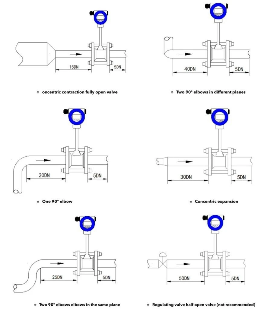
Vortex flow meters require specific lengths of straight pipe upstream and downstream of the installation point. Insufficient straight runs can disturb the flow field in the pipeline, affecting measurement accuracy.
The inner diameters of the upstream and downstream piping should be the same. If there is adifference, the piping diameter Dp and the meter body diameter D, should satisfy: 0.98 DDp1.05Db. Upstream and downstream pipes must be concentric with the meter body, andeccentricity should be less than 0.05 Db.
The sealing gasket between the meter and the flange should not protrude into the pipeline during installation. Its inner diameter should be 1–2 mm larger than the meter body diameter.
Installation design for pressure and temperature taps: when pressure and temperature transmitters need to be installed, the pressure tap should be located 3–5D downstream, and the temperature tap 6–8D downstream. D is the nominal diameter of the meter, in mm.
The meter can be installed horizontally, vertically, or at an angle on the pipeline.
When measuring gases in vertical pipelines, the flow direction is generally not limited. However, if a small amount of liquid is present, the flow should go from bottom to top to prevent liquid from entering the meter tube.
When measuring liquids, the pipeline must be fully filled. For vertical or inclined installations, the flow should go from bottom to top. If there is a small amount of gas, the meter should be installed at the lower part of the pipeline to prevent gas from entering the measuring tube.
For high- or low-temperature fluids, proper insulation is necessary. The temperature inside the converter (transmitter housing) should generally not exceed 70°C. Low temperatures can cause condensation inside the converter, reducing the insulation resistance of the PCB and affecting normal operation.
The selection and installation location of a vortex flow meter should be matched appropriately to the actual operating conditions. The meter’s materials, flow range, and compatible media must align with the installation environment to ensure stable operation under specific conditions. For high-temperature, high-pressure, or highly corrosive media, special attention should be paid to the meter’s material and sealing to prevent equipment damage due to improper material selection.


