

-
Date:2026-01-09

-
Page View:92

The accuracy of an mag flowmeter is influenced by multiple factors. These factors can generally be classified into fluid properties, installation conditions, electromagnetic interference, meter-related factors, and environmental conditions. A detailed explanation is provided below:
I. Fluid Properties
1. Conductivity
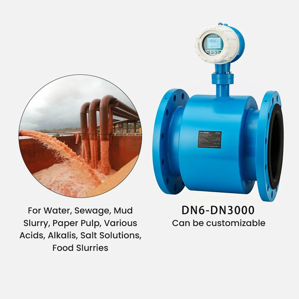
Mag flowmeter are only suitable for conductive fluids (typically with a conductivity ≥ 5 μS/cm). If the fluid conductivity is too low (such as pure water or oils), the signal strength will be insufficient for accurate measurement. If the conductivity is too high (such as concentrated acids or alkalis), electrode polarization may occur, leading to measurement errors.
2. Viscosity Effects
High-viscosity fluids (such as asphalt or syrup) tend to form a laminar boundary layer along the inner pipe wall during flow. If this boundary layer covers the electrodes, the induced signal may be weakened, resulting in measurement errors.
3. Flow Velocity Range
The optimal flow velocity for mag flowmeter is typically between 0.5 and 10 m/s. At low velocities (< 0.5 m/s), the induced signal is weak and the signal-to-noise ratio is low. At excessively high velocities (> 10 m/s), the fluid may erode the electrodes and pipeline or cause flow disturbances, negatively affecting measurement accuracy.
4. Air Bubbles and Solid Particles
The presence of air bubbles or solid particles (such as sand or fibers) in the fluid can disrupt the magnetic field distribution and cause signal fluctuations. For example, when the air content exceeds 5%, measurement errors may increase significantly.
II. Meter-Related Factors
1. Improper Selection of Electrode and Lining Materials
The electrode and liner materials must be compatible with the chemical properties of the measured fluid. When measuring highly corrosive fluids such as strong acids or alkalis, electrodes made from non-corrosion-resistant materials may deteriorate, causing signal distortion. Similarly, if the liner material lacks sufficient corrosion resistance, it may degrade or fail, allowing the fluid to contact the measuring tube directly and reducing measurement accuracy.
2. Meter Aging and Wear
Over time, key components of an mag flowmeter—such as electrodes, liners, and coils—may experience aging and wear. Electrodes can become fouled or oxidized, liners may thin or crack, and coil insulation performance may degrade, all of which can negatively impact measurement accuracy.
3. Signal Processing Circuitry
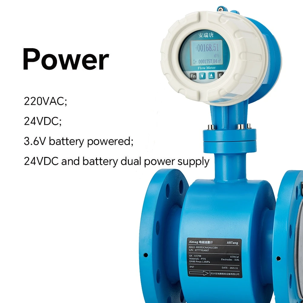
Advanced mag flowmeter use digital signal processing (DSP) technology, which can automatically compensate for temperature and pressure variations and provides stronger resistance to interference. As a result, their accuracy is typically 0.5%–1% higher than that of traditional analog instruments.
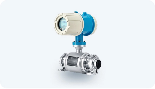
electromagnetic meter
mag flowmeter
III. Environmental Factors
1. Temperature Variations
Temperature changes can affect the resistance and magnetic permeability of the sensor coils, thereby altering the magnetic field strength. In general, for every 10 °C increase in temperature, measurement error may increase by approximately 0.1%–0.5%. In addition, extreme temperatures (below −20 °C or above 80 °C) may degrade the performance of electronic components.
2. Humidity and Corrosive Gases
High-humidity environments can cause condensation inside the instrument, while corrosive gases such as chlorine or hydrogen sulfide may damage sensor electrodes or liner materials, reducing measurement stability and reliability.
3. Electromagnetic Interference
If an mag flowmeter operates in an environment with strong electromagnetic fields—such as near high-power motors, variable frequency drives (VFDs), or high-voltage cables—external interference may affect signal integrity and lead to measurement errors. For example, installation near unshielded cables can result in errors exceeding 1%.
IV. Installation Conditions
1. Straight Pipe Length Requirements
Depending on the meter size and upstream piping conditions, the recommended straight pipe length is generally 5–10 pipe diameters (D) upstream and 3–5D downstream. If these requirements are not met during installation, measurement accuracy may be adversely affected.
2. Installation Location
Installation near pump outlets, control valves, or in vertical pipelines where air bubbles are likely to accumulate should be avoided. For horizontal installations, the electrode axis should be parallel to the horizontal plane to prevent sediment from covering the electrodes.
3. Grounding and Shielding
The sensor must be properly grounded (ground resistance ≤10 Ω), and shielded cables should be used for signal transmission to minimize electromagnetic interference. Poor grounding can result in measurement errors exceeding 5%.
V. Maintenance and Management
1. Cleaning and Inspection
Regularly clean the inner wall of the sensor to prevent deposits from covering the electrodes. Check cable connections to ensure they are secure and to avoid poor contact.
2. Periodic Calibration
Electromagnetic flow meters should be calibrated regularly (typically every 1–2 years) to eliminate zero drift or linearity changes caused by long-term operation. Without calibration, measurement errors may accumulate to more than 5% over time.
3. Cable and Connector Inspection
Periodically inspect signal cables for damage and check that connectors are firmly secured to prevent signal interruption or electromagnetic interference.
The accuracy of an mag flowmeter is influenced by multiple factors, including the environment, fluid properties, installation, instrument characteristics, and maintenance. To ensure precise measurements, it is essential to select the appropriate model (e.g., high-precision or corrosion-resistant types), strictly follow installation guidelines, and perform regular maintenance and calibration. For special fluids, such as low-conductivity or high-viscosity liquids, using a dedicated electromagnetic flow meter or auxiliary equipment may help improve accuracy.


