

-
Date:2026-01-07

-
Page View:76

An electromagnetic digital flow meter is a flow measurement device designed based on Faraday’s law of electromagnetic induction, widely used for measuring the flow of conductive liquids. In industrial automation and process control, the flow meter’s output signals are essential for remote monitoring, data logging, and automated control. Electromagnetic digital flow meter offer a variety of output signal types.
Core Types of Output Signals for Electromagnetic Digital Flow Meter
The output signal of an electromagnetic digital flow meter serves as a crucial bridge between the measurement unit and the control system. The main types are as follows:
1. Analog Signals
4–20 mA Current Signal: The most widely used in industrial applications, it offers strong resistance to interference and can transmit over distances up to 1000 meters (per IEC 61158). The zero point corresponds to 4 mA, full scale to 20 mA, and line faults can be detected at 0 mA.
0–10 V Voltage Signal: Suitable for short-distance transmission (usually less than 30 meters), it is more affected by line impedance, but cost-effective and commonly used in small-scale equipment.
2. Pulse Signals
Frequency Output: For example, a 0–1 kHz square wave, where each pulse represents a fixed volume of flow (e.g., 1 pulse = 0.1 m³). This is ideal for flow accounting or batch control.
Switch Output: Used for alarms or status indication (e.g., relay output triggered when flow exceeds preset limits).
3. Digital Communication Protocols
HART Protocol: Digital signals are superimposed on the 4–20 mA signal, supporting two-way communication and remote parameter configuration (e.g., Rosemount 8750 series).
Modbus RTU / Profibus PA: Designed for industrial automation networks, with transmission speeds up to 12 Mbps (Profibus PA) and support for multi-device networking.
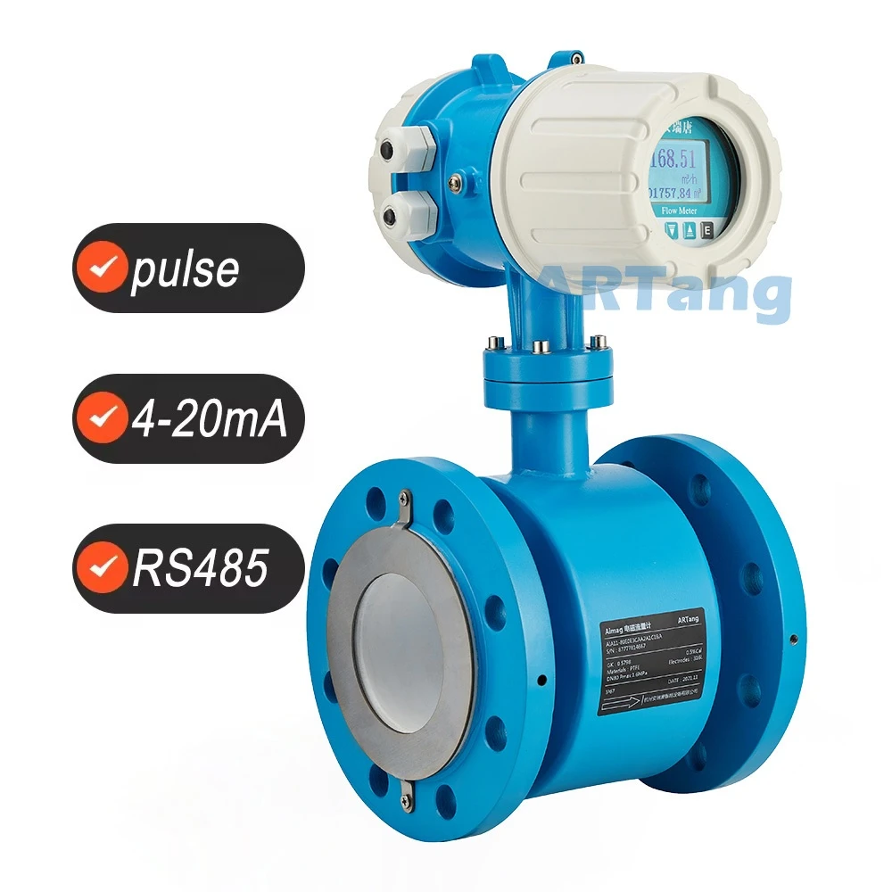
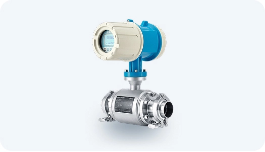
Electromagnetic Digital Flow Meter
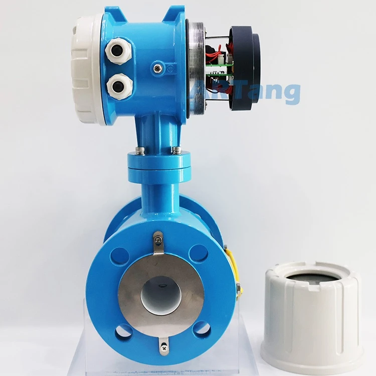
Magnetic Digital Flowmeters
How to Choose the Output Signal for an Electromagnetic Digital Flow Meter
1. Analog Signal Output
4–20 mA Current Signal: The most commonly used analog signal, offering strong resistance to interference and suitable for long-distance transmission. Widely applied in industrial control systems.
0–10 V / 0–5 V Voltage Signal: Suitable for short-distance transmission or applications requiring low-voltage analog signals.
2. Digital Signal Output
Serial Communication Interfaces:
RS-232 / RS-485: Supports protocols like Modbus and HART, enabling data exchange with PLCs or host computers.
Wireless Transmission (e.g., GPRS): Ideal for remote monitoring in locations where wiring is difficult.
Pulse / Frequency Output:
Pulse Output: Each pulse represents a fixed volume (e.g., 1 L), used for cumulative flow measurement.
Frequency Output: Frequency is proportional to flow rate (e.g., 0–5000 Hz), suitable for control applications.
3. Special Function Outputs
HART Protocol: Digital communication superimposed on the 4–20 mA signal, supporting parameter configuration.
Combined Output: Some models support simultaneous analog and digital signal output.
In summary, the choice of an electromagnetic digital flow meter output signal should be based on actual application requirements and site conditions. Factors such as measurement accuracy, data transmission distance, and interface compatibility must be considered to ensure reliable and stable flow measurement data.


