

-
Date:2025-09-03

-
Page View:338

1. Influence of Gas Content in Oil Products
When the volume of gas in oil products is relatively large, the impact can be significant. Under high fluid pressure, bubbles passing through the flowmeter may burst upon collision, leading to internal pitting and potential equipment damage. In operation, this can also cause zero drift of the flowmeter and increase measurement errors.
The main causes of gas generation in fluids include:
Intrinsic gas content: If the fluid itself contains a certain amount of gas, unstable operating conditions may cause the oil to carry gas from pipeline or equipment high points into the mass flowmeter.
Control valve cavitation: Typically, a control valve is installed upstream of the flowmeter to regulate pressure or flow. When the valve opening is small and there is a large pressure difference across it, according to Bernoulli’s principle, the pressure downstream decreases while velocity increases, which can lead to cavitation.
Temperature and pressure conditions: If the fluid entering the mass flowmeter has excessively high temperature and low pressure—below the medium’s saturation vapor pressure—gas formation will occur.
2. Influence of Temperature and Pressure
Fluctuations in medium temperature, ambient temperature, and medium pressure are also important factors affecting the measurement accuracy of a flowmeter. Variations in temperature and pressure can easily cause abnormal vibrations of the measuring tubes during operation, leading to measurement errors.
3. Influence of Installation Conditions and Operating Environment
The installation of a Coriolis effect mass flowmeter directly affects its measurement accuracy, mainly in the following aspects:
Stress Impact
If the reserved space for installation is either too large or too small, or if the pipeline connections on both sides are misaligned (higher or lower), and the flowmeter is forcibly installed, the mass flowmeter may be subjected to tensile, compressive, and shear forces from the connected pipelines. Such stresses can deform the vibrating tubes inside the flowmeter, causing zero drift and reducing measurement accuracy.
Vibration Impact
During operation, a Coriolis effect mass flowmeter may be affected by vibrations from upstream or downstream pipelines, or from the operation of other flowmeters. When the vibrating tubes receive additional external vibrations while measuring fluid flow, the measurement error of the flowmeter can increase.
Electromagnetic and Radio Frequency Interference
If electrical equipment such as motors, transformers, transmitters, or high-voltage cables is installed near the Coriolis effect mass flowmeter, electromagnetic waves and radio frequency waves may interfere with the self-excited resonance of the vibrating tubes. This can cause deviations in the detected signal, thus affecting measurement accuracy.
4. Other Influencing Factors
Effect of Oil Viscosity and Density
When oil products pass through the flowmeter, differences in viscosity directly affect the measurement results. High-viscosity oils tend to cause a positive error, with relatively small variations in the error range. Low-viscosity oils, on the other hand, tend to cause a negative error, with larger variations in the error range.
Under the same operating pressure, temperature, and volumetric flow conditions, if the density of the oil increases, the kinetic energy of the fluid entering the flowmeter at a given velocity also increases. According to the principle of energy conservation, the Coriolis force generated in the vibrating tubes will change accordingly, thereby affecting measurement accuracy.
Effect of Flowmeter Parameters
The intrinsic parameters of the Coriolis effect mass flowmeter, such as zero-point stability and turndown ratio, are also key factors influencing measurement accuracy during operation.
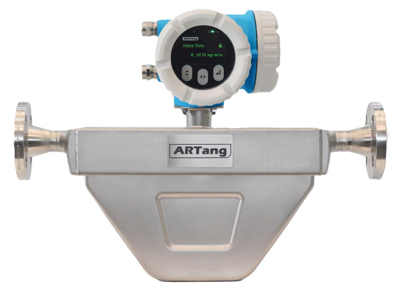
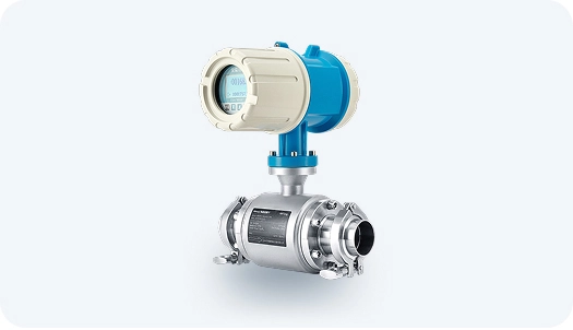
mass flowmeters

coriolis mass flow measurement
Solutions to Influencing Factors
1. Solutions for Gas Content in Oil Products
Gas elimination methods: The primary method to eliminate entrained gas is to install a degasser upstream of the Coriolis effect mass flowmeter, ensuring that only pure liquid enters the meter. In some stations, cavitation generated by control valves is mitigated by modifying the valve core structure.
Another method is to establish back pressure using a control valve installed downstream of the flowmeter. This keeps the medium pressure higher than its saturation vapor pressure, thereby preventing cavitation. Since the saturation state of oil is affected by temperature, there should be no heat sources near the flowmeter, and direct sunlight exposure should be avoided.
2. Solutions for Temperature and Pressure Influence
The main approach to minimizing temperature and pressure effects is compensation. If the operating temperature and pressure are fixed, external temperature and pressure values can be manually input into the flowmeter’s sensor software. If significant fluctuations occur, the flowmeter can be configured to poll real-time temperature and pressure values detected by instruments, applying dynamic compensation.
At present, most Coriolis effect mass flowmeters are equipped with platinum resistance sensors inside the measuring tubes for automatic temperature compensation. Additionally, a pressure transmitter is typically installed downstream of the flowmeter to provide automatic pressure compensation.
3. Solutions for Installation Conditions and Operating Environment
1. During installation, ensure accurate alignment of the process pipeline. The flanges on both sides must be parallel, and the flowmeter must not be used to forcibly straighten the upstream or downstream piping. Fixed supports should be installed on both sides of the flowmeter.
2. Isolation valves should be installed both upstream and downstream of the flowmeter to facilitate zero adjustment.
3.During operation or calibration, never use the upstream isolation valve for flow regulation, as throttling may generate bubbles that can enter the flowmeter.
4. Strong electromagnetic devices such as motors, variable-frequency drives, transformers, and high-voltage cables must not be installed near the flowmeter.
5. For parallel installations involving multiple flowmeters, maintain adequate spacing between units to prevent mutual vibration interference during simultaneous operation. If conditions allow, avoid operating adjacent flowmeters at the same time.
6. During zero adjustment, first close the downstream isolation valve to ensure the flowmeter chamber is fully filled with liquid and free of bubbles, then close the upstream isolation valve before performing the zeroing procedure.


